


Search News
Global Industrial Intelligence Hub (GIIH)Industry Portal
Global Industrial Intelligence Hub (GIIH)Status
Standard Access
Upgrade to PremiumNewsHow to select engineered components for smart home devices
Time
Click Count
Select engineered components for smart homes by starting with the device’s operating conditions: where it will be installed, how it will be powered, what it must detect or control, and which other devices it must communicate with. A component that performs well on a development board can fail after it is enclosed, mounted near metal, or required to run for years on a small battery.
Define the system-level limits first, then compare components under those conditions. For a battery-powered door sensor, sleep current, reliable event detection, and radio behavior during infrequent transmissions may dominate the decision. For a mains-powered lighting controller, thermal performance, electrical isolation, switching endurance, and behavior after a power interruption often carry more weight.
Translate the device’s job into component requirements
Describe the complete operating cycle before selecting individual parts. Include startup, normal operation, communication, fault recovery, firmware updates, and any periods when the device must remain inactive. Record the installation environment as well: a bathroom sensor faces humidity and condensation; a controller inside a wall box has limited airflow and may sit close to electrical wiring.
Turn those conditions into measurable acceptance criteria. A motion sensor, for example, needs a detection area defined at its intended mounting height and orientation. A smart lock motor needs enough torque at the lowest expected battery voltage, including friction from the latch and misalignment of the door. A connectivity module needs adequate link performance from its final location, rather than only in open air.
Separate requirements that determine whether a design is viable from preferences that can be traded off. If a device must continue to operate locally during an internet outage, local control is a system requirement. The choice of a particular processor becomes a trade-off within that constraint.
Choose connectivity around the installed device
Wireless selection affects power, enclosure design, setup, network behavior, and interoperability. Compare the available technologies against the device’s traffic pattern and the network already present in the intended installation. A device sending occasional state changes has different needs from a camera or a frequently updated display.
A protocol name alone does not establish interoperability. Verify the specific application features, supported device roles, commissioning method, and software versions on both sides. A device that can join a network does not necessarily expose every control or measurement in the form required by another system. Where a common application standard is required, confirm that the intended device type and functions are supported by both the component software and the target ecosystem.
A module’s advertised radio range is a poor substitute for an installed test. Antenna orientation, nearby batteries, ground-plane layout, metal fasteners, wall materials, and the enclosure all affect the link. An external antenna can improve placement options, but introduces a connector, cable loss, assembly steps, and possible mechanical damage. If an integrated antenna is selected, reserve its specified clearance early in the board and enclosure design.
Test weak-signal recovery as well as normal communication. A device that reconnects only after a power cycle can create service calls even when its peak throughput is adequate. Observe behavior after an access point or network coordinator restarts, and after the device returns from a long sleep.
Build the power budget from real events
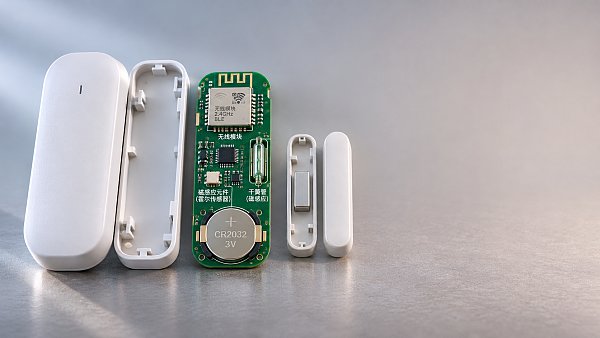
For battery-powered products, compare total energy over a representative operating cycle rather than choosing by the lowest quoted sleep current. Include sensor sampling, processor wake-up, radio association, retransmissions, indicator lights, and any motor or relay operation. Current drawn by regulators, pull-up resistors, external flash, and sensors that remain active also contributes during sleep.
A useful estimate adds the energy for each state: current multiplied by supply voltage and time, repeated at the expected frequency. Use measured values where possible, especially for radio connection and retry behavior. A weak link can extend the active period enough to change the battery-life estimate substantially.
Battery capacity also changes with discharge current, temperature, and the minimum voltage the electronics can tolerate. A motorized lock can reset during an actuation pulse even when the battery appears adequate under a light load. Measure voltage at the electronics during the pulse, including contact and wiring resistance, and assess whether local energy storage or a different power architecture is required.
For mains-powered devices, standby consumption still matters, but heat and isolation often become the tighter constraints. A compact wall-mounted controller combines power conversion losses with switching losses in an enclosed space. Assess component temperatures at the highest intended ambient temperature and load, with the enclosure assembled and mounted as it will be in service.
Evaluate sensors in their mechanical and environmental context
Start with the measurement that the product actually needs. A temperature sensor’s accuracy specification does not guarantee accurate room-temperature readings if the sensor sits beside a processor or voltage regulator. Board heat, airflow, enclosure openings, sunlight, and wall contact can all shift the reading. Compare candidate sensors in the intended position after the device reaches thermal equilibrium.
For motion detection, consider the sensing principle and the installation geometry. Passive infrared sensing responds to changes in infrared energy across its field of view; a stationary person may cease to produce a strong signal. Other sensing approaches can provide different coverage characteristics, but reflections, partitions, moving objects, and unwanted detection outside the intended area need evaluation. Specify acceptable detection and false-trigger behavior for the actual room and mounting location.
Humidity sensors require a path to ambient air, while the enclosure must also protect electronics from contamination and moisture. A sealed enclosure can delay or distort the reading; a large opening can admit dust or water. Condensation exposure, recovery time, and any protective membrane should be evaluated together rather than treated as independent specifications.
Review sensor resolution, accuracy, repeatability, drift, and response time as separate properties. Fine resolution produces small displayed increments, but does not establish accuracy. For a control loop, repeatability and response time may be more useful than a highly precise reading that arrives too slowly. Calibration can correct some offset, but adds production steps and does not necessarily remove drift across temperature or operating life.
Match processing capacity to the full software workload
Select a processor with enough memory and processing headroom for the application, connectivity stack, security functions, diagnostics, and updates. Assess peak memory use during demanding operations such as network commissioning or firmware installation, not just the memory occupied by the normal application image.
Firmware updates deserve attention early. Some update designs retain the running image while receiving and validating a replacement, increasing nonvolatile storage requirements. Recovery behavior matters too: loss of power during an update should leave a defined path back to a working image or a controlled service procedure.
Integrated wireless system-on-chip devices reduce board area and part count, while separate processor and radio components allow more flexibility in performance and interfaces. The appropriate choice depends on software support, power states, required peripherals, and how closely the radio and application workloads interact. Confirm that the chosen software stack supports the needed features within the available memory, rather than relying only on processor clock speed.
Plan for hardware interfaces before freezing the board. Sensor buses, motor-control outputs, debug access, and secure-element connections compete for pins and board space. A lower-cost processor with insufficient interfaces can force an external expander or a board redesign.
Include security and recovery in component selection
Security requirements affect silicon, memory, manufacturing, and ongoing software support. Establish how each device receives its identity and credentials, how firmware authenticity is verified, and how compromised or obsolete software can be replaced. Hardware-backed key storage and secure boot can reduce exposure, provided the complete provisioning and update process uses those features correctly.
Ask for clear documentation of security-update support and the process for reporting and correcting vulnerabilities. A component with strong hardware features but an unsupported connectivity stack may create a maintenance problem. Also consider reset behavior: returning a device to factory settings should remove sensitive credentials while leaving a workable path for recommissioning.
Assess switching, materials, and assembly together
For smart plugs, lighting controls, and motorized devices, select switching components against the actual load. A relay rated for a resistive load may face much higher stress when switching a capacitive power supply or an inductive motor. Consider inrush current, contact wear, arcing, operating temperature, and the required state after a power failure. A solid-state switch avoids mechanical contact wear, but leakage current and heat dissipation can affect compatibility with the connected load.
Enclosure material influences radio performance, heat transfer, impact resistance, and long-term fit. Gaskets and seals affect water and dust protection only when their compression, joint geometry, and assembly tolerances are controlled. A seal that performs on a prototype can leak after a change in screw torque or enclosure material.
Connectors and fasteners deserve the same attention as active electronics. Repeated battery replacement stresses contacts and latches; vibration or thermal cycling can loosen marginal connections. Review tolerances across the housing, circuit board, and mounting features so that assembly does not bend the board or place continuous force on a connector.
Make the comparison with evidence from the assembled product
Shortlist components using documented operating limits, available design files, software support, expected lifecycle, and replacement options. For constrained or sole-source parts, establish whether an alternative can fit electrically, mechanically, and in software. A pin-compatible substitute may still require changes to firmware, calibration, radio matching, or certification evidence for the finished device.
Compare candidates through a small set of product-level trials: measure current over representative events, exercise the radio in difficult installation positions, expose sensors to expected environmental conditions, and run switching or actuation cycles with the intended load. Record both the result and the conditions that produced it. This makes a failed test useful: poor radio performance, for example, can then be traced to antenna placement, enclosure effects, or network conditions instead of prompting an unsupported module change.
Before release, repeat the decisive measurements on production-representative assemblies. Changes in board layout, battery contacts, enclosure tooling, or component revision can alter the behavior that made the original selection acceptable.
Recommended News
 Nov 11, 2026How to select engineered components for smart home devicesChoose engineered components for smart homes with confidence. Explore practical tips on connectivity, power, sensors, security, and real-world testing.
 Nov 01, 2026How to check if a smart living integrator supports your devicesFind out if a smart living integrator supports your devices. Check model compatibility, automation features, hubs, and costs before you commit.
 Oct 22, 2026How to check if a home control touch panel works with your devicesWill a home control touch panel work with your devices? Learn how to check models, hubs, key functions, and offline control before you buy—and avoid costly compatibility mistakes.
 Oct 05, 2026How to plan connected home devices for villas with weak Wi-Fi coverageConnected home devices for villas need reliable planning beyond Wi-Fi. Discover practical strategies for wired backbones, resilient controls, vendor coordination, and future-ready coverage.
 Sep 02, 2026Which Auto System Parts Fail Most Often in Tropical Climates?What auto systems parts have the highest failure rate in tropical climates? Discover the batteries, cooling, brake, electrical, and A/C parts that need proactive maintenance.
 Aug 18, 2026How to verify whether home control systems testing standards meet safety requirementsHome control systems testing standards: learn how to verify real safety compliance, spot hidden certification gaps, and make smarter release decisions for smart home products.
 Aug 03, 2026Z-Wave Home Control Systems: What to Compare Before You BuyZ-Wave home control systems compared the smart way: learn how to evaluate compatibility, security, mesh stability, automation, and true long-term value before you buy.
 Jul 15, 2026How to Choose a Home Automation Supplier for Multi-Room and Retrofit ProjectsHome automation supplier selection made simple: learn how to compare integration, retrofit readiness, software openness, support, and total cost for scalable multi-room projects.
 Jul 15, 2026Global Home Control Systems Explained: Types, Protocols, and Best-Fit Use CasesGlobal home control systems explained clearly: compare types, protocols like Matter, Zigbee, and Wi-Fi, plus best-fit use cases to choose smarter, safer home automation.
 Jul 14, 2026Connected Home Technology Supplier Comparison: What to Check Before You ShortlistConnected home technology supplier comparison: learn what to check before shortlisting vendors, from interoperability and security to supply resilience and long-term service fit.
 Jul 13, 2026How Energy Efficient Building Automation Cuts HVAC and Lighting Costs in Commercial BuildingsEnergy efficient building automation helps commercial buildings cut HVAC and lighting costs, reduce energy waste, and improve comfort with smarter controls, analytics, and faster ROI.
 Jul 12, 2026Building Automation Data Logging: Which Metrics Matter for Energy Performance?Building automation data logging reveals which metrics truly drive energy performance. Discover key signals, common mistakes, and practical insights to cut waste and optimize operations.
 Jul 04, 2026How to Choose Portable Solar Generators for Home Backup, Camping, or Mobile WorkPortable solar generators buying guide: learn how to choose the right capacity, output, battery type, and charging speed for home backup, camping, or mobile work.
 Jul 02, 2026Building Automation Zigbee vs Wi-Fi: Which Is Better for Stable Device Networks?Building automation Zigbee vs Wi-Fi: discover which delivers more stable, low-maintenance device networks for smart buildings, and choose the right fit for scale, power use, and reliability.
 Jul 01, 2026Prefabricated House Buying Guide: Materials, Cost Drivers, and Build TimePrefabricated house buying guide covering materials, key cost drivers, build time, and supplier risks. Learn how to compare quotes smarter and choose the right solution with confidence.
 Jun 30, 2026Home Control Systems Price Breakdown: Hardware, Installation, and Upgrade CostsHome control systems price explained: compare hardware, installation, subscriptions, and upgrade costs to budget smarter and avoid hidden fees before you buy.
 Jun 27, 2026How to Choose a Smart Living Management System for Multi-Room Energy and Device ControlSmart living management system selection starts with interoperability, room-level energy visibility, and scalability. Learn how to compare vendors, avoid costly mistakes, and choose a platform that improves control and efficiency.
 Jun 26, 2026Smart Living Certification Requirements: Key Standards, Tests, and Compliance StepsSmart living certification requirements explained: key standards, safety and EMC tests, regional marks, and practical compliance steps to speed approval and reduce launch risk.
 Jun 25, 2026Smart Home Gateway vs Hub: What’s the Difference and Which One Do You Need?Smart home gateway vs hub explained: learn the key differences, protocol support, automation benefits, and how to choose the right smart home gateway for a scalable, future-ready home.
 Jun 24, 2026How to Compare Smart Living Systems in the UAE for Villas, Apartments, and Gated HomesSmart living systems UAE guide: compare villa, apartment, and gated home solutions by security, integration, scalability, and long-term value to choose smarter with confidence.
 Jun 23, 2026Smart Home Basics: Which Devices Actually Improve Daily Convenience and Energy Control?Smart home essentials that truly improve daily convenience and energy control: discover which devices deliver real value, cut waste, and fit your routines before you buy.
 Jun 21, 2026Sustainable Home Decor for Eco-Conscious Consumers: Which Materials Are Better for Daily Use?Sustainable home decor for eco-conscious consumers starts with smarter materials. Compare wood, bamboo, metal, textiles, glass, and cork for healthier, durable daily living.
 Jun 14, 2026Prefab Glamping Cost Breakdown: What to Compare Before Choosing a Modular SitePrefab glamping cost breakdown explained: compare hidden site, logistics, compliance, and maintenance costs before choosing a modular site that protects ROI.
 Jun 11, 2026Smart Hotel Systems Explained: What to Automate First for Guest Experience and Energy SavingsSmart hotel systems explained: learn what to automate first—HVAC, lighting, digital check-in, and energy monitoring—to elevate guest experience, cut energy waste, and improve hotel margins.
{item.publish_time}{item.title}{item.description}