


Search News
Global Industrial Intelligence Hub (GIIH)Industry Portal
Global Industrial Intelligence Hub (GIIH)Status
Standard Access
Upgrade to PremiumNewsWhen does shaft runout require custom precision parts?
Time
Click Count
Shaft runout becomes a critical design and quality concern when it threatens bearing life, sealing performance, vibration control, or assembly accuracy. The central question is not whether any measurable runout exists—every real component has some variation—but whether the resulting motion is compatible with the function of the assembled system. When a standard shaft tolerance no longer protects that function, custom precision parts shafts become a practical engineering requirement rather than an unnecessary upgrade.
For technical evaluators, the decision should begin with the operating system, not with a blanket request for “tighter tolerances.” A shaft that performs reliably in a low-speed conveyor may fail prematurely in a compact pump, electric drive, optical instrument, surgical device, high-speed spindle, or automated inspection fixture. The same measured deviation can be harmless in one application and unacceptable in another because load, speed, bearing arrangement, sealing method, thermal conditions, and assembly interfaces all change the consequence of runout.
Runout is not one measurement
Runout is often discussed as though it were a single shaft characteristic. In practice, it is a measured variation relative to a chosen datum and measurement setup. Radial runout describes how much a cylindrical surface appears to move toward and away from a reference axis during rotation. Axial runout, sometimes called face wobble, concerns variation on a shaft shoulder, flange, or end face. Total indicator reading may be used during inspection, but it must not be treated automatically as a complete explanation of shaft geometry.
A reading can be influenced by several underlying conditions: centerline offset, bending, local roundness error, taper, surface damage, imperfect centers, or instability in the inspection setup. A shaft can also show acceptable runout at one journal and unacceptable behavior at a functional feature farther from the datum. This is especially relevant for long, stepped, hollow, or slender shafts, where accumulated geometric error and deflection become more visible along the length.
That distinction matters in sourcing. A drawing that merely says “low runout” leaves too much open to interpretation. It does not identify the datum axis, the controlled feature, the inspection support points, the rotational condition, or the relationship between journals, gear seats, seal tracks, and mounting faces. Custom work is justified when these relationships—not just a diameter tolerance—must be deliberately designed and verified.
The point at which standard shafting stops being enough
Standard catalog shafts and broadly toleranced machined components are appropriate when the assembly can absorb modest alignment variation. Flexible couplings, compliant mounts, low rotational speeds, generous bearing clearances, and non-contacting interfaces can make a conventional solution entirely reasonable. A custom precision shaft should not be selected simply because precision sounds safer; unnecessary requirements can increase machining complexity, inspection burden, lead time, and cost without improving field performance.
The case changes when runout consumes a meaningful portion of the system’s available functional margin. A useful way to assess this is to ask: how much motion can the most sensitive interface tolerate after accounting for all other contributors? Those contributors may include housing misalignment, bearing internal clearance or preload variation, coupling error, thermal growth, rotor balance condition, fixture variation, and deflection under load. If the allowable motion is already largely consumed before shaft geometry is considered, a generic part is unlikely to provide a robust result.
Custom precision parts shafts are commonly warranted in the following situations:
- The shaft carries rolling-element bearings that require controlled journal geometry and a stable relationship between bearing seats.
- A lip seal, mechanical seal, labyrinth arrangement, or close-clearance sealing surface is sensitive to orbital shaft motion or surface defects.
- The shaft supports a gear, pulley, encoder, rotor, impeller, disc, or other feature whose concentricity affects transmitted motion.
- The system runs at speeds where a small geometric error can become a recurring vibration excitation.
- Assembly relies on repeatable positioning, such as robotic joints, test equipment, medical mechanisms, semiconductor handling equipment, or precision automation.
- A high-consequence application cannot rely on post-assembly selection, rework, or field adjustment to compensate for shaft variation.
The most convincing trigger is usually not an isolated drawing requirement. It is a pattern: short bearing or seal life, unexplained vibration, intermittent sensor faults, inconsistent torque, difficult assembly, or a component that passes individual dimensional checks but behaves poorly once installed.
How runout turns into a reliability problem
At a bearing journal, excessive radial motion can introduce cyclic loading that the bearing arrangement was not intended to carry. The effect depends on bearing type, load direction, preload strategy, shaft stiffness, housing accuracy, and rotational speed. The shaft is only one part of the bearing system, but a poor journal-to-journal relationship can make an otherwise sound bearing selection appear unreliable.
Seals are often less forgiving than designers expect. A rotating seal track may need more than a nominal diameter and surface finish; it may require controlled roundness, cylindricity, hardness, texture, and runout relative to the actual rotating axis. If the shaft orbit causes the contact condition to vary continuously, leakage, heat generation, or accelerated lip wear can follow. In fluid handling equipment, a seal issue may be misdiagnosed as a seal-material problem when the shaft surface and motion are the real contributors.
In electrically driven systems, runout can interact with rotor balance, air-gap consistency, encoder positioning, and noise performance. In automotive and mobility applications, the concern may involve drivetrain smoothness, brake-related interfaces, e-axle components, or sensor accuracy. In medical and laboratory equipment, a minor recurring displacement can affect dosing, imaging, sample handling, or instrument calibration. Environmental systems such as pumps, blowers, sorting equipment, and treatment machinery introduce another challenge: corrosion, contaminants, and temperature cycles may gradually magnify an initially manageable condition.
This is why a runout issue should not be evaluated only at incoming inspection. The more meaningful question is whether the shaft maintains the required geometry during manufacture, heat treatment, coating, transport, assembly, and operation.
Specify the functional datum before specifying a tighter tolerance
A strong custom shaft specification begins with datum strategy. The functional rotational axis is frequently established by one or two bearing journals, by precision centers, or by a defined mounting feature. Runout of a seal land, spline, gear seat, flange face, or sensor feature should then be controlled relative to that axis. Controlling every feature to an arbitrary external diameter can create inspection confusion and may not protect the actual assembly function.
Technical evaluators should distinguish between requirements that are truly functional and those inherited from an earlier drawing. For example, a shaft shoulder may need axial control because it locates a bearing. A pulley seat may need radial control relative to bearing journals. A threaded end may require only enough precision for fastening, not the same geometric control as the seal track. Applying the tightest requirement everywhere is expensive and can make manufacturing less stable, particularly where multiple operations, hardened surfaces, or thin-walled sections are involved.
The drawing package should also state which condition matters: free-state geometry, geometry after a press fit, geometry after heat treatment, or assembled runout in a fixture. These are not interchangeable. A shaft can meet a free-state requirement and still show unacceptable installed behavior if an interference fit, keyway, clamping method, or component stack-up distorts the part.
Questions worth resolving before requesting quotations
- Which features establish the real axis of rotation in the finished assembly?
- Which interface is most sensitive: bearing, seal, gear mesh, encoder, rotor, or locating face?
- Is the concern geometric runout, dynamic deflection, imbalance, or a combination of these?
- Will heat treatment, plating, grinding, coating, or assembly fits change the controlled condition?
- What inspection method will be accepted, and does it represent the functional setup?
- Are material traceability, cleanliness, corrosion resistance, or sector-specific documentation part of the release requirement?
Manufacturing choices determine whether the requirement is repeatable
Custom precision does not mean one manufacturing route fits every shaft. Material selection affects machinability, distortion risk, surface treatment options, stiffness, wear behavior, corrosion resistance, and response to heat treatment. A material that is suitable for a static structural shaft may be a poor choice for a hardened seal journal or a component exposed to aggressive media. The final choice should follow the operating environment and the critical surfaces, not only the strength value listed on a material certificate.
Process sequence is equally important. Rough machining may release residual stress. Heat treatment can introduce distortion. Grinding may be needed to establish final bearing-seat geometry, while superfinishing or controlled polishing may be required for a sealing surface. Plating and coatings require careful consideration because thickness variation, adhesion, post-process finishing, and edge conditions can alter dimensions or surface behavior. Long shafts may need support strategies during turning and grinding to avoid creating apparent precision in one setup and bending-related error after release.
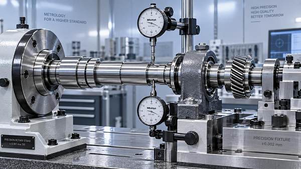
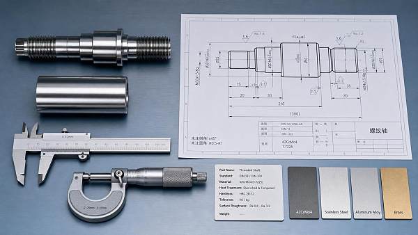
Inspection must be matched to the feature and the risk. A dial indicator setup remains useful for straightforward runout checks, but the setup must be controlled. Coordinate measurement, form measurement, roundness evaluation, or dedicated functional gauges may be appropriate when the geometry is complex or when multiple features interact. The inspection record should identify the datum scheme and measurement condition. A report with a favorable result but no meaningful setup description offers limited assurance.
Avoid treating runout as the only variable
A recurring sourcing mistake is to react to vibration or wear by tightening shaft runout alone. The symptom may instead arise from imbalance, poor coupling alignment, housing distortion, inadequate shaft stiffness, damaged bearing seats, insufficient surface quality, or an assembly method that introduces bending. A tighter custom shaft will not correct a misaligned housing or a rotor whose mass distribution is unsuitable for its operating speed.
Conversely, dismissing a shaft issue because the part looks straight can be equally costly. Visual straightness is not a geometric requirement, and a shaft can feel smooth during hand rotation while still producing a repetitive error in service. The practical solution is to connect failure evidence to the functional stack-up: inspect wear patterns, confirm where measurements are taken, compare unloaded and assembled conditions, and review what changed between acceptable and problematic builds.
For global supply chains, this review should extend beyond the drawing. Technical language, datum conventions, inspection capability, packaging, transit handling, and batch-release documentation can all affect the outcome. A supplier may understand a diameter limit yet interpret the rotational reference differently. Clear communication before production is often more valuable than a late dispute over a measurement report.
A more disciplined sourcing decision
The right threshold for custom precision parts shafts is reached when runout control is necessary to preserve a defined function and cannot be reliably achieved through standard material, generic tolerances, or downstream adjustment. That threshold is usually visible in the relationship between the shaft and its most sensitive mating component—not in the shaft drawing alone.
A sensible evaluation package combines the functional drawing, critical dimensions and geometric controls, material and surface requirements, expected loading and speed, assembly sequence, inspection expectations, and any known failure observations. If some of these inputs are unknown, it is better to identify the uncertainty openly than to impose arbitrary limits that neither solve the problem nor support consistent production.
At Global Industrial Intelligence Hub, our automotive engineering perspective is part of a broader effort to connect technical detail with supply-chain decisions across mobility, medical technology, logistics, smart systems, and environmental equipment. The useful outcome is not simply a more detailed specification. It is a clearer line between a shaft that is dimensionally acceptable and one that is genuinely fit for its working system. Before committing to a custom solution, confirm the functional axis, the critical interface, the inspection condition, and the process steps most likely to alter geometry. Those four points usually reveal whether tighter control is justified.
Recommended News
 Sep 22, 2026How Brake Drum Material and Machining Affect Semi Trailer Service LifeSemi trailer spare parts guide: discover how brake drum material and precision machining improve braking reliability, reduce wear, and extend trailer service life.
 Sep 10, 2026Evaluating Compatibility and Certification Requirements for Replacement Brake Drums on BPW-Axle Semi-TrailersDiscover certified semi trailer spare parts for BPW-axle trailers—ensuring brake drum compatibility, EN 15085-2 certification & optimal thermal performance.
 Sep 09, 2026When does shaft runout require custom precision parts?Custom precision parts shafts become essential when runout affects bearings, seals, vibration, or assembly accuracy. Learn how to specify reliable, high-performance shaft solutions.
 Jul 14, 2026RoHS Precision Parts Explained: Compliance Requirements, Test Reports, and Buying RisksRoHS precision parts explained: learn compliance requirements, how to read test reports, spot supplier gaps, and avoid costly buying risks before shipment approval.
 Jul 14, 2026Precision Machining Factory Selection Guide: Tolerances, Materials, and Inspection CapabilityPrecision machining factory selection starts with tolerance control, material expertise, and inspection capability. Learn how to compare suppliers, reduce risk, and choose with confidence.
 Jul 13, 2026Forged Engineered Components Explained: When Forging Outperforms Casting or MachiningForged engineered components deliver superior strength, fatigue resistance, and reliability. Discover when forging outperforms casting or machining for critical industrial parts.
 Jul 12, 2026Laminated Core Components: How to Choose Grades, Thickness, and ApplicationsLaminated core components explained: learn how to choose steel grades, thickness, and application fit to cut losses, improve efficiency, and make smarter design decisions.
 Jul 11, 2026Diamond Saw Blades for Stone, Tile, and Concrete: How to Choose the Right Typediamondsawblades buying guide for stone, tile, and concrete. Learn how to match blade type, cutting method, and machine for cleaner cuts, longer life, and fewer costly mistakes.
 Jul 09, 2026Product Selection Criteria for Stamped Parts: 7 Factors That Affect Fit and CostProduct selection criteria for stamped parts: discover 7 key factors that shape fit, tolerance, tooling, and total cost—make smarter sourcing decisions with less risk.
 Jul 09, 2026Sheet Metal Custom Parts: How to Choose Tolerances, Finishes, and Lead TimesSheet metal custom parts guide: learn how to choose the right tolerances, finishes, and lead times to reduce cost, improve fit, and avoid sourcing delays.
 Jul 08, 2026How to Do Product Category Analysis for Precision Parts Sourcing and Supplier ShortlistingProduct category analysis precision parts helps buyers classify components, compare true supplier fit, and shortlist faster with better cost, lead time, and compliance accuracy.
![]() Jul 07, 2026How to Evaluate a Battery Protection Parts Supplier for Quality, Testing, and Supply StabilityBattery protection parts supplier evaluation starts with quality, testing, and supply stability. Learn the key checks, red flags, and sourcing criteria for safer, more reliable decisions.
Jul 07, 2026How to Evaluate a Battery Protection Parts Supplier for Quality, Testing, and Supply StabilityBattery protection parts supplier evaluation starts with quality, testing, and supply stability. Learn the key checks, red flags, and sourcing criteria for safer, more reliable decisions. Jul 04, 2026Custom Precision Parts Prototype: Tolerance, Material, and Lead Time BasicsCustom precision parts prototype basics made practical: learn how tolerance, material, and lead time choices reduce risk, improve testing, and speed smarter production decisions.
 Jul 04, 2026Custom Engineered Components vs Standard Parts: When Is Customization Worth It?Custom engineered components vs standard parts: discover when customization lowers lifecycle cost, reduces downtime, and creates stronger competitive advantage.
 Jul 03, 2026How to Source Precision Machined Parts in the Middle East: Tolerances, Materials, and Supplier ChecksPrecision machined parts Middle East sourcing starts with tighter supplier checks. Learn how to compare tolerances, materials, certifications, and total cost for safer, smarter procurement.
 Jul 02, 2026Performance Factor Analysis for Surface Treatment: Key Variables That Affect Coating ResultsPerformance factor analysis for surface treatment reveals how substrate condition, cleanliness, profile, environment, and process settings shape coating results. Learn the key variables to improve adhesion, consistency, and production decisions.
 Jun 29, 2026Material Selection Analysis by Weight: When Lighter Parts Improve Total System PerformanceMaterial selection analysis by weight reveals when lighter parts truly improve total system performance, cutting energy, load, and lifecycle cost while avoiding hidden tradeoffs.
 Jun 27, 2026Engineered Components Drawing Review: 8 Checks to Catch Tolerance and DFM Issues EarlyEngineered components drawing review made practical: discover 8 smart checks to catch tolerance, GD&T, and DFM issues early, reduce rework, and improve launch readiness.
 Jun 26, 2026DIN Precision Parts: Tolerances, Materials, and How to Read Spec RequirementsDIN precision parts explained clearly: learn tolerances, material selection, surface requirements, and how to read DIN specs to reduce sourcing risk and choose suppliers with confidence.
 Jun 25, 2026Custom Precision Parts for Electronics: Tolerance, Material, and Process BasicsCustom precision parts electronics guide covering tolerance, material, and process basics. Learn how to reduce sourcing risk, improve fit and reliability, and choose suppliers with confidence.
 Jun 24, 2026Rapid Prototyping Near Me: How to Compare Lead Time, Materials, and Tolerance OptionsRapid prototyping near me: compare lead time, materials, and tolerance options with a practical framework to choose faster, smarter suppliers and reduce costly prototype delays.
 Jun 23, 2026Sheet Metal Components Manufacturing: Tolerance, Finish, and Process Options ExplainedSheet metal components manufacturing explained: compare tolerance, finish, and process options to reduce sourcing risk, control cost, and choose suppliers with confidence.
 Jun 23, 2026Ballscrews Selection Guide: How Lead, Accuracy, and Load Affect Motion PerformanceBallscrews selection guide covering lead, accuracy, and load. Learn how to improve speed, repeatability, and service life with practical tips for better motion performance.
 Jun 22, 2026PCB Assembly Process Explained: SMT, THT, Testing, and Common Defects to Watch ForPCB assembly explained clearly: learn SMT, THT, testing methods, and common defects that affect reliability, compliance, and product performance across industries.