


Search News
Global Industrial Intelligence Hub (GIIH)Industry Portal
Global Industrial Intelligence Hub (GIIH)Status
Standard Access
Upgrade to PremiumNewsHow to specify mounting hole tolerances for custom precision brackets
Time
Click Count
A bracket can pass a dimensional inspection and still refuse to assemble. The holes may be the correct diameter, yet their pattern is shifted relative to the mounting face. Alternatively, a drawing may demand such tight tolerances that a straightforward clearance-hole bracket becomes an unnecessarily expensive machining job.
For technical evaluators sourcing custom precision parts brackets, the challenge is to specify what the assembly actually needs—not simply the smallest tolerance a supplier can quote. Hole size, position, datum selection, mating-part variation, and inspection conditions must work together. The most useful drawing makes those relationships explicit, so manufacturing and quality teams can reach the same conclusion about an acceptable part.
Start with the joint: what must the holes accomplish?
Before assigning tolerances, identify whether the mounting holes provide clearance, locate the bracket, accommodate adjustment, or engage threaded fasteners. These functions demand different controls.
A useful distinction is whether the fastener merely holds the bracket or also locates it. Clearance bolts generally should not be assumed to deliver precise, repeatable alignment. If an optical sensor, bearing support, or automotive fixture needs a stable location after replacement, separate locating features may be more effective than tightening every bolt-hole tolerance.
Also establish the acceptance condition: must every interchangeable bracket fit every mating component, or is selective assembly allowed? Global sourcing programs usually benefit from interchangeability, but it must be designed into the tolerance stack rather than assumed.
Separate hole diameter from hole location
A diameter tolerance controls hole size. It does not, by itself, adequately control where that hole sits. Conversely, a positional tolerance does not replace the need to specify diameter limits.
For a clearance hole, the minimum diameter is usually the critical assembly limit. The maximum diameter can still matter because excessive clearance may reduce washer support, permit unwanted movement before tightening, or compromise the material ligament near an edge.
Location is commonly controlled using geometric dimensioning and tolerancing, or GD&T. Basic dimensions establish the theoretically exact pattern, while a position tolerance defines the permissible departure from that pattern relative to selected datums.
This avoids an important limitation of coordinate tolerancing. Independent ± tolerances in two directions produce a rectangular acceptance region. A diametrical position tolerance produces a cylindrical zone, which generally corresponds more directly to the clearance available around a round fastener. Do not treat the same numerical value as equivalent between these approaches.
Practical rule: specify size for fit and position for assembly location. Add orientation, form, or surface controls only where the functional requirement is not already adequately covered.
Choose datums that reproduce the assembled bracket
Datum selection is often more consequential than reducing a positional tolerance by a few hundredths of a millimeter. A highly accurate hole pattern referenced to an irrelevant edge can still be misplaced in the actual assembly.
For a machined bracket seated against a base and located by two orthogonal surfaces, a plausible datum arrangement is:
- Primary datum A: the mounting face that contacts the base.
- Secondary datum B: the functional side surface that establishes lateral location.
- Tertiary datum C: an end surface that establishes the remaining in-plane location.
That arrangement is appropriate only if those surfaces actually participate in locating the bracket. If the assembly locates through pins, a bore, or a pilot diameter, the datum scheme should reflect those features instead. Avoid choosing convenient manufacturing edges merely because they are easy to measure.
For bent sheet-metal brackets, consider which flange seats against the mating component and whether the part is evaluated in its free state or under defined restraint. Bend-angle variation and springback can move holes on another flange even when their local spacing is accurate.
The mounting face may also need a flatness requirement. A warped bracket can rock during inspection or distort when tightened. Hole-pattern acceptance alone will not necessarily prevent this behavior.
Use maximum material condition where clearance justifies it
Under ASME GD&T conventions, specifying hole position at maximum material condition (MMC) can align acceptance with the assembly’s available clearance. For an internal feature such as a hole, MMC is its smallest permitted size.
As the hole becomes larger than MMC, additional positional tolerance—often called bonus tolerance—becomes available. This is useful when extra diameter genuinely provides additional room for a fastener. It is not automatically appropriate for precision locating holes or features whose center location matters independently of clearance.
A simplified clearance-hole example
Consider a bracket with the following illustrative specification:
- Hole diameter: Ø6.60–6.80 mm.
- Position tolerance: Ø0.40 mm at MMC, relative to functional datums A, B, and C.
- Basic dimensions defining the nominal hole pattern.
At a hole size of Ø6.60 mm, the available positional tolerance is Ø0.40 mm. At Ø6.75 mm, the size departure from MMC is 0.15 mm, giving a total positional tolerance of Ø0.55 mm.
For this simple internal-feature example, the virtual-condition boundary is:
6.60 − 0.40 = Ø6.20 mm.
This boundary combines the hole’s size and geometric tolerance into a functional limit. It can support assembly assessment and, where appropriate, functional-gage design.
However, this calculation is not a complete joint analysis. Mating-fastener size, fastener-axis location, orientation, engagement length, and datum relationships still matter. A nominal Ø6.00 mm fastener does not prove compatibility unless its maximum effective envelope and permitted location variation are included.
Also distinguish bonus tolerance from datum mobility. A material-boundary modifier applied to a datum reference can allow movement of the datum reference frame under specified conditions. It is not simply another bonus value to add without evaluating the assembly.
Allocate the tolerance budget across both components
A bracket drawing cannot guarantee assembly independently of the mating part. The available clearance must absorb variation from both components, and sometimes from the fasteners themselves.
For a simplified fixed-fastener joint with aligned datum systems, negligible angular effects, and compatible engagement geometry, the minimum hole diameter minus the maximum fastener diameter provides a diametrical clearance budget. The combined positional allocations must fit within that budget.
If a hole has a minimum diameter of 6.60 mm and the fixed fastener has a maximum diameter of 6.00 mm, the budget is 0.60 mm. Allocating Ø0.40 mm to bracket-hole position leaves Ø0.20 mm for fixed-fastener positional variation in this simplified model.
These are diametrical positional values, not radial offsets. The example also assumes the mating datum relationships are controlled. Face misalignment, a tilted stud, or a long engagement can consume clearance that the simple calculation does not represent.
Floating-fastener assemblies, in which bolts pass through clearance holes in both parts, require a different stack-up. Do not apply a fixed-fastener calculation indiscriminately. For complex patterns, evaluate both simultaneous fit and the relationship between locating features and mounting holes.
Worst-case analysis is appropriate when guaranteed interchangeability is required. Statistical methods can support production decisions, but only when their distribution assumptions, process stability, and acceptable assembly risk are justified.
Address bracket geometry beyond the hole pattern
Several details can defeat an otherwise sensible mounting-hole specification:
- Long engagement: angular error becomes more significant as the fastener travels through greater thickness.
- Stand-off assembly: a threaded-hole axis may need a projected tolerance zone to control interference above the bracket surface.
- Counterbores and countersinks: their relationship to the through-hole affects seating and available clearance.
- Coatings: plating or paint may reduce hole clearance or change locating fits.
- Burrs: entry and exit burrs can obstruct insertion or prevent flush seating.
- Thin sections: clamping and measurement forces may distort the part.
Specify whether dimensional requirements apply before or after finishing. For precision interfaces, identify masking or post-finish machining where necessary. Edge-break requirements should remove harmful burrs without allowing an excessive chamfer that reduces bearing support.
For threaded holes, make clear how position applies under the chosen drawing standard; do not assume measuring the tap-drill opening establishes thread-axis compliance.
Make manufacturing and inspection part of the specification
When comparing supplier proposals for custom precision parts brackets, ask how the critical features will be produced relative to one another. Machining a mounting face and hole pattern in a coordinated setup can reduce transfer error. Multiple setups are not inherently unacceptable, but their datum transfer must be controlled.
Process choice should follow function. Drilling may be sufficient for generous clearance holes. Reaming can improve size and finish, but does not automatically correct a misplaced hole. Boring or interpolation may offer better control in suitable circumstances. For formed brackets, punching before bending may hold local spacing while leaving final three-dimensional position sensitive to bend variation.
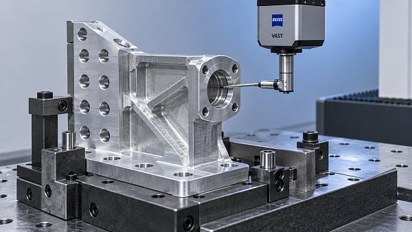
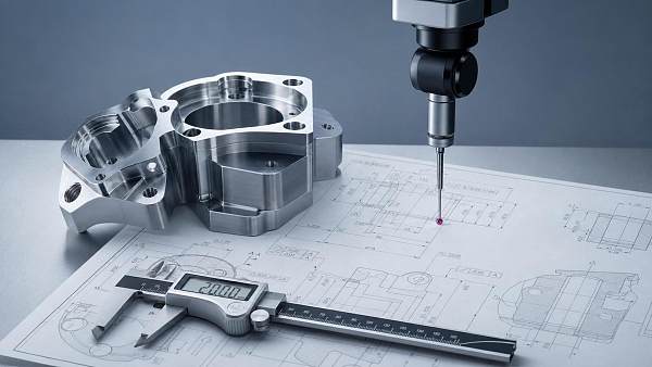
Inspection must reproduce the specified datum reference frame. A coordinate measuring machine can assess hole position, but the result depends on datum establishment, probing strategy, alignment, and the evaluation method. A best-fit alignment that minimizes pattern error may be inappropriate when the drawing requires alignment to functional datums.
Functional gages can efficiently assess assembly-related boundaries, especially for MMC-controlled patterns. They do not necessarily verify every size, form, or surface requirement, so complementary measurements may still be needed.
Ask suppliers to document:
- The equipment and method used for hole size and position.
- How datums and any specified restraint are established.
- Whether inspection occurs after bending, heat treatment, and finishing.
- Measurement uncertainty relative to the tolerance.
- The sampling plan and treatment of borderline results.
Remove ambiguity before releasing the drawing
Specify the governing drawing standard and edition. ASME Y14.5 and the ISO GPS framework both support geometric specifications, but their conventions and default rules should not be mixed casually. ISO-based drawings may invoke standards addressing geometrical tolerances, datums, and maximum-material requirements, as applicable.
A final technical review should confirm that the hole callouts include size limits, basic locations where needed, position requirements, datum references, and material-condition modifiers. Review related mounting-face controls, thread requirements, finishing conditions, and any assembly restraint at the same time.
For cross-border sourcing, also align the drawing, inspection report, and purchase specification on units and acceptance criteria. A capable supplier should be able to explain the proposed inspection approach—not merely confirm that the tolerance is “achievable.”
From GIIH’s industrial-intelligence perspective, a useful specification connects engineering intent with manufacturing evidence. The objective is not maximum precision everywhere. It is enough precision in the right relationships to deliver reliable assembly, defensible inspection, and predictable sourcing costs.
Recommended News
 Nov 13, 2026US Extends Antidumping and Countervailing Duty Orders on Chinese ChassisUS antidumping and countervailing duties on certain Chinese chassis remain in place. Explore potential sourcing and pricing impacts and what buyers should verify.
 Nov 08, 2026How to choose stamped parts for high-vibration applicationsChoose application based stamped parts for high-vibration environments. Explore fatigue risks, material selection, joint design, and testing to improve reliability.
 Oct 18, 2026Which automotive fastener standards define bolt strength classes?Explore automotive fastener standards ISO 898-1, SAE J429, and ISO 3506-1. Compare bolt strength classes, decode markings, and learn what to verify before approving substitutions.
 Nov 18, 2026How to specify mounting hole tolerances for custom precision bracketsSourcing custom precision parts brackets? Learn how to specify mounting hole tolerances, datums, and GD&T for reliable assembly, clear inspection, and lower manufacturing costs.
 Sep 22, 2026How Brake Drum Material and Machining Affect Semi Trailer Service LifeSemi trailer spare parts guide: discover how brake drum material and precision machining improve braking reliability, reduce wear, and extend trailer service life.
 Sep 10, 2026Evaluating Compatibility and Certification Requirements for Replacement Brake Drums on BPW-Axle Semi-TrailersDiscover certified semi trailer spare parts for BPW-axle trailers—ensuring brake drum compatibility, EN 15085-2 certification & optimal thermal performance.
 Sep 09, 2026When does shaft runout require custom precision parts?Custom precision parts shafts become essential when runout affects bearings, seals, vibration, or assembly accuracy. Learn how to specify reliable, high-performance shaft solutions.
 Jul 14, 2026RoHS Precision Parts Explained: Compliance Requirements, Test Reports, and Buying RisksRoHS precision parts explained: learn compliance requirements, how to read test reports, spot supplier gaps, and avoid costly buying risks before shipment approval.
 Jul 14, 2026Precision Machining Factory Selection Guide: Tolerances, Materials, and Inspection CapabilityPrecision machining factory selection starts with tolerance control, material expertise, and inspection capability. Learn how to compare suppliers, reduce risk, and choose with confidence.
 Jul 13, 2026Forged Engineered Components Explained: When Forging Outperforms Casting or MachiningForged engineered components deliver superior strength, fatigue resistance, and reliability. Discover when forging outperforms casting or machining for critical industrial parts.
 Jul 12, 2026Laminated Core Components: How to Choose Grades, Thickness, and ApplicationsLaminated core components explained: learn how to choose steel grades, thickness, and application fit to cut losses, improve efficiency, and make smarter design decisions.
 Jul 11, 2026Diamond Saw Blades for Stone, Tile, and Concrete: How to Choose the Right Typediamondsawblades buying guide for stone, tile, and concrete. Learn how to match blade type, cutting method, and machine for cleaner cuts, longer life, and fewer costly mistakes.
 Jul 09, 2026Product Selection Criteria for Stamped Parts: 7 Factors That Affect Fit and CostProduct selection criteria for stamped parts: discover 7 key factors that shape fit, tolerance, tooling, and total cost—make smarter sourcing decisions with less risk.
 Jul 09, 2026Sheet Metal Custom Parts: How to Choose Tolerances, Finishes, and Lead TimesSheet metal custom parts guide: learn how to choose the right tolerances, finishes, and lead times to reduce cost, improve fit, and avoid sourcing delays.
 Jul 08, 2026How to Do Product Category Analysis for Precision Parts Sourcing and Supplier ShortlistingProduct category analysis precision parts helps buyers classify components, compare true supplier fit, and shortlist faster with better cost, lead time, and compliance accuracy.
![]() Jul 07, 2026How to Evaluate a Battery Protection Parts Supplier for Quality, Testing, and Supply StabilityBattery protection parts supplier evaluation starts with quality, testing, and supply stability. Learn the key checks, red flags, and sourcing criteria for safer, more reliable decisions.
 Jul 04, 2026Custom Precision Parts Prototype: Tolerance, Material, and Lead Time BasicsCustom precision parts prototype basics made practical: learn how tolerance, material, and lead time choices reduce risk, improve testing, and speed smarter production decisions.
 Jul 04, 2026Custom Engineered Components vs Standard Parts: When Is Customization Worth It?Custom engineered components vs standard parts: discover when customization lowers lifecycle cost, reduces downtime, and creates stronger competitive advantage.
 Jul 03, 2026How to Source Precision Machined Parts in the Middle East: Tolerances, Materials, and Supplier ChecksPrecision machined parts Middle East sourcing starts with tighter supplier checks. Learn how to compare tolerances, materials, certifications, and total cost for safer, smarter procurement.
 Jul 02, 2026Performance Factor Analysis for Surface Treatment: Key Variables That Affect Coating ResultsPerformance factor analysis for surface treatment reveals how substrate condition, cleanliness, profile, environment, and process settings shape coating results. Learn the key variables to improve adhesion, consistency, and production decisions.
 Jun 29, 2026Material Selection Analysis by Weight: When Lighter Parts Improve Total System PerformanceMaterial selection analysis by weight reveals when lighter parts truly improve total system performance, cutting energy, load, and lifecycle cost while avoiding hidden tradeoffs.
 Jun 27, 2026Engineered Components Drawing Review: 8 Checks to Catch Tolerance and DFM Issues EarlyEngineered components drawing review made practical: discover 8 smart checks to catch tolerance, GD&T, and DFM issues early, reduce rework, and improve launch readiness.
 Jun 26, 2026DIN Precision Parts: Tolerances, Materials, and How to Read Spec RequirementsDIN precision parts explained clearly: learn tolerances, material selection, surface requirements, and how to read DIN specs to reduce sourcing risk and choose suppliers with confidence.
 Jun 25, 2026Custom Precision Parts for Electronics: Tolerance, Material, and Process BasicsCustom precision parts electronics guide covering tolerance, material, and process basics. Learn how to reduce sourcing risk, improve fit and reliability, and choose suppliers with confidence.
{item.publish_time}{item.title}{item.description}